PV system types
Open Source Solar Project is focused on stand-alone PV systems, nonetheless it is important to distinguish the different system types and associated terminology as it will help when designing a system and selecting equipment.
Contents
Note on direct current coupling vs. alternating current coupling
There are two overarching categories of stand-alone and multi-mode systems that are presented below - direct current coupled (DC-coupled) and alternating current coupled (AC-coupled). These two terms refer to the way in which the PV charging source is integrated into the system - a DC-coupled system will rely upon a charge controller and a direct connection to the battery bank, whereas an AC-coupled system will rely upon an interactive (grid-tie) inverter which will convert the PV array output into AC to power the loads, any excess will then be used to charge the battery bank. DC-coupled systems are the most common and versatile design, but AC-coupling carries some advantages in the case of larger systems that supply stead loads during the day. This is because an AC-coupled system passes the energy that the array generates through an interactive inverter which is then able to directly power loads, this is is more efficient (~90-98%) than passing it through a charge controller, battery bank, and then through the inverter (~85-95%) like in a DC-coupled system. AC-coupling generally only makes sense in the case of larger more complex systems and requires additional design considerations to ensure that the grid-tied inverter is able to reduce its output if there are insufficient loads or the battery bank is full.
Grid-tied PV systems
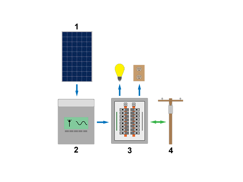
PV systems installed that have a grid connection are called grid-tied systems. The inverters that come with these types of systems are called interative as they are capable of interacting with the grid by matching its voltage and frequency. They automatically shutdown if they lose their connection to the grid in order to ensure the safety of any electrical workers that might be working to correct the issue. These systems therefore do not provide backup power in the case of a power outage. These systems cannot store energy, thus as the system produces energy, it must either be consumed on the presmises or it will be fed back into the grid - through a meter - to be used by other customers. The majority of PV systems installed globally are of this type.
Stand-alone systems
PV systems installed in areas that lack a grid connection are called stand-alone systems, but are also commonly referred to as battery-based or off-grid systems. These systems take many different forms, but they almost always incorporate some type of storage, typically a battery bank, and one or more charging sources. In addition to solar PV, these systems may include a generator, wind, or hydro as well. These systems with multiple charging sources may also be referred to as hybrid systems. Stand-alone systems can use alternating current and direct current as charging sources and can supply alternating and direct current for loads. The various different stand-alone system types are depicted below.
Direct current only
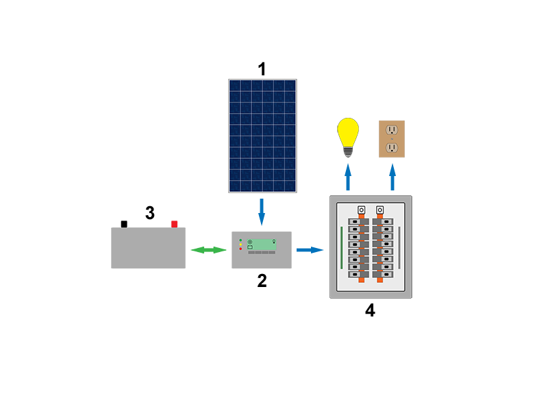
A common system in less developed off-grid areas - common with systems less than 100W of PV. An economical option to provide lighting and energy for small appliances. Using only direct current has the advantage avoiding energy losses due inefficiencies created by an inverter (inverters are typically only around 85%-95% efficient) and the energy that is required to power an inverter when it is standing by. The disadvantage of not having an inverter is that most appliances are designed for use with alternating current, therefore the available DC appliance market is often much smaller.
Any connections to a battery bank should run through what is called a low voltage disconnect which will disconnect loads if the voltage of the battery bank drops too low in order to protect the batteries. Often times, as depicted in the image, a low voltage disconnect is integrated into the charge controller.
DC-coupled with an inverter
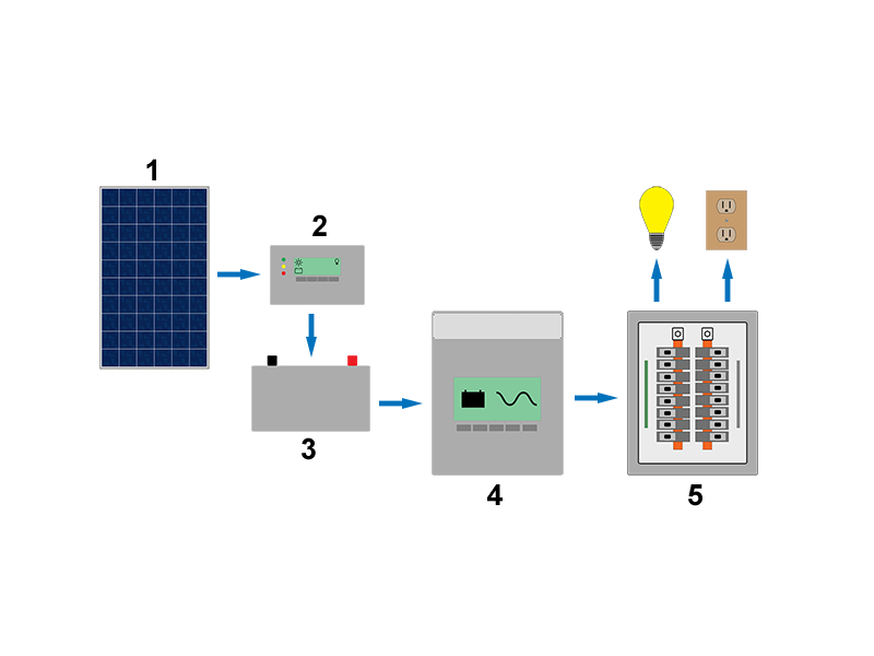
An inverter becomes an essential part of any PV system that is intended to power anything beyond small lighting and appliance loads. A standard inverter enables the use of alternating current appliances. An inverter does have efficiency losses and stand-by consumption losses, but it makes a PV system far more versatile.
DC-coupled with an inverter-charger
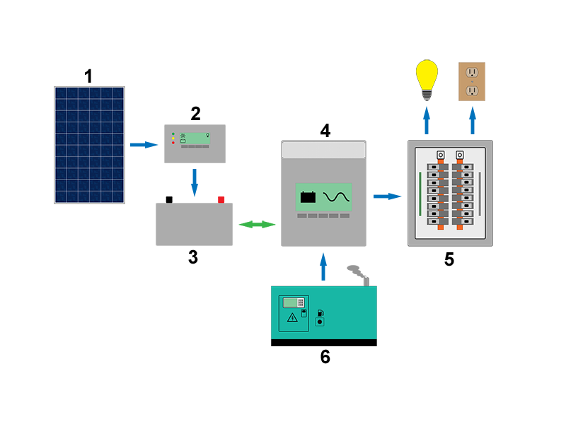
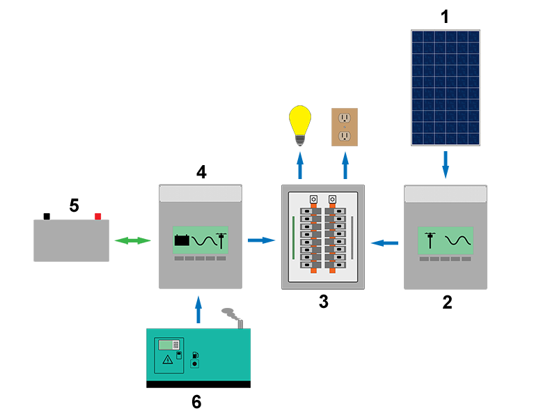
A system with larger energy needs or a system that supplies critical loads, like at a medical clinic, will often incorporate a generator to ensure that energy needs are met at all times. An inverter charger is capable of rectifying (the opposite process of invertering) alternating current into direct current in order to charge the battery bank. The inverter-charger can be programmed to automatically start a generator if the voltage drops below a certain value or if the loads increase to a certain value.
AC-coupled with an inverter-charger
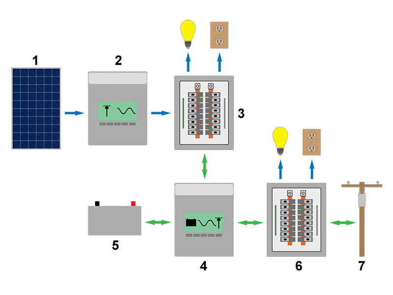
The array in this configuration is connected to a interactive (grid-tie) inverter, which will directly supply loads in the distribution panel before passing energy on to the inverter-charger, which will convert it to direct current to charge the battery bank if necessary. Note that there is no charge controller, the inverter-charger will manage the battery bank in this configuration.
Multi-mode systems
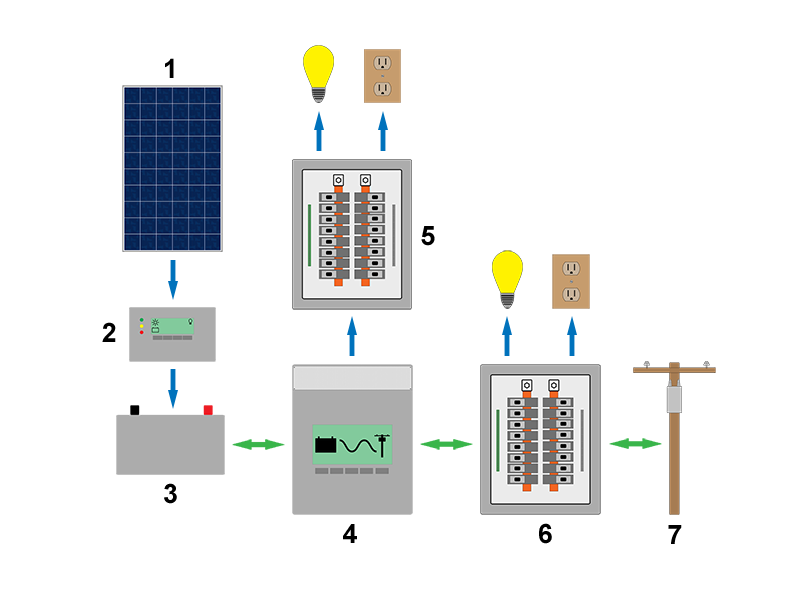
Multi-mode systems can integrate many different energy sources like a system with an inverter-charger, but they are also capable of interacting with the grid. They can charge the battery bank off of the grid, but can also be programmed to feed energy back into the grid if the battery bank is full and there is excess energy that is not being consumed by loads. As these systems integrate PV, storage and the grid, they are rather complex and can require significant programming depending on the application. The two most common applications for a multi-mode system are for back-up power systems that integrate PV and for grid-tied systems in areas that offer very little compensation for excess energy feed back into the grid or prohibit the exportation of excess production. If very little compensation is offered to the user, then the inverter is typically set in an autoconsumption configuration, which prioritizes the local consumption of the energy generated by the PV array before any is exported. If exporting to the grid is prohibited, then the inverter can be configured into a zero sell configuration that will ensure that no energy is fed back into the grid.
A key aspect of a multi-mode system is that loads must be seperated into seperate panels: the critical load panel and the non-critical load panel. The multimode inverter will continue to supply electricity to the critical load panel to ensure the functioning of these loads, while any loads in the normal distribution panel will lose power. The reason for dividing loads into these two categories is that the output of the inverter and the energy stored in the battery bank is limited, therefore the loads must be limited accordingly.
With DC-coupling
In this configuration a charge controller and the multimode inverter are capable of charging the battery bank. It is ideal that they are able to communicate to ensure proper functioning of the system.
With AC-coupling
In this configuration there is no charge controller. An interactive (grid-tie) inverter is connected to the critical loads panel. If grid power fails, the interactive inverter will continue functioning as it will continue seeing the voltage supplied from the multimode inverter.
