Busbar
Busbars are an essential component of electrical systems as they allow safe and easy parallel connections of circuits. There are many different designs of busbars that all serve this same purpose. It is important any busbar used is rated to handle the current that it must carry and that the busbar is properly isolated from all other system components. Busbars should only be installed within enclosures that are protected from unauthorized or accidental access as they have live exposed parts.
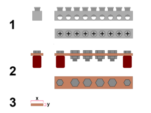
The amount of current that a standard copper busbar can carry can be determined by measuring the height and width of the busbar in mm - see 3 illustration. If these two values are multiplied it will give a mm² value that can be used with the table for wire ampacity in Overview of wire and overcurrent protection sizing and selection.
The formula for calculating the cross-sectional area of a busbar is:
Cross sectional area = x (width) × y (height)
Example 1: A busbar is measured to have a height of 5 mm and a width of 10 mm. What is its mm² cross sectional area?
- Cross sectional area = 5 mm × 10 mm
- Cross sectional area = 50 mm²
