Grounding system
A grounding system creates a low-resistance connection between system equipment and/or a system conductor - called a neutral or grounded conductor - to the earth. A grounding system is not necessary for an electrical system to function, the electrical distribution systems in some countries lack any type of grounding and others have complex grounding systems with additional measurement devices to protect users. In offgrid installations, it is common for small-scale DC-only PV systems operating at below 50V to lack a grounding system as it would increase the cost substantially without providing significant benefit. As system size, voltage, and cost increase the benefits of a grounding system grow. The electrical code for every country will contain information about the requirements and appropriate equipment for that location.[1]
Additionally, it is necessary to consult the manual for any charge controller or inverter before deciding upon a grounding scheme as they may have different requirements for grounding. There are some small inverters - modified sine wave and square wave - that will be destroyed if they are connected in a system that has both an AC and a DC system ground.
The preferred grounding system for an offgrid system is called a TN-S system, which has a grounded conductor (neutral) and a seperate ground that is run with each circuit.[2] A TN-S grounding system carries has two distinct purposes each of which carries unique benefits:
- System grounding - A proper grounding system provides a means to dissipate excess static electricity created by friction or lightning. This helps to create a stable system voltage and protect system equipment from damage. A system ground is created by creating a connection between the earth and one of the conductors of an electrical system.
- Equipment grounding - A proper grounding system in which all non-current carrying metallic components of a system are grounded and bonded together enables the overcurrent protection devices in an electrical system to automatically identify and disconnect faults before they pose a risk to users. When a fault - failure of insulation, loose connection - occurs, a properly grounded system provides a path for the current - through the grounding system or earth - to return to the grounded conductor. This should effectively create a short-circuit and cause an overcurrent protection device to open (disconnect) the circuit.
A grounding system can also create a shock hazard because if the fault is not able to find a path back to its source through the equipment ground, the hazard will go undetected until a person touches the equipment and establishes a path to ground. A residual current device (RCD) can be incorporated into a system to identify faults sooner and to help minimize this risk.
Components of a TN-S grounding system

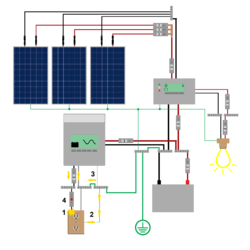
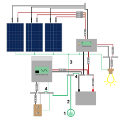
1. The ungrounded conductor touches a grounded piece of equipment. 2. The equipment grounding conductor carries the current back to the busbar. 3. The system bonding jumper connects the ungrounded conductor to the grounded conductor. 4. A low resistance path for current to flow is created. Current surges from the inverter and the overcurrent protection device for the circuit opens (disconnects) the circuit.
A proper grounding system requires various different components that are connected together in order for the system to work effectively. The system to work safely, it is necessary to properly incorporate overcurrent protection devices.
- Grounding electrode - The connection point between the earth and the electrical system. There are many different types of electrodes - copper rods, steel rods, a copper plate, the metallic pipes of a building, or a proper connection to the rebar used in the foundation of a building.
- Grounding electrode conductor - The connection that runs from the grounding electrode to the location of the rest of the electrical equipment - typically a wire that runs from the grounding electrode to a grounding busbar in the main distribution panel.
- Equipment grounding conductor - The connection that runs from the grounding busbar in the main service panel to all of the non-current carrying metallic components of a system (conduit, inverter housing, charge controller housing, enclosures, etc.).
- System bonding jumper - The connection between a current carrying conductor in an electrical system and the grounding electrode conductor - typically a wire in the main distribution panel that runs from the grounding electrode conductor busbar to the grounded conductor busbar.
Notes
- ↑ Cahiers Techniques 173: Earthing Systems Worldwide and Evolutions https://www.mikeholt.com/documents/mojofiles/electricalearthingworldwide.pdf
- ↑ SMA Grounding in Off-grid Systems: Design of TN and TT Off-Grid https://files.sma.de/downloads/SI-OffGrid-Grounding-TI-en-11.pdf
