Dimensionamiento y selección de un controlador de carga MPPT simplificado
Un controlador de carga MPPT está clasificado para funcionar a una tensión de CC del sistema, corriente máxima y tensión máxima. Los controladores de carga MPPT pueden cargar el sistema de almacenamiento de energía con cualquier configuración de módulos FV en serie y paralelo que no exceda la tensión máxima y la corriente máxima o caiga por debajo de la tensión de carga requerido del sistema de almacenamiento de energía. Exceder la clasificación de tensión de un MPPT debido a las bajas temperaturas puede dañarlo. Muchos controladores de carga permiten que se exceda la clasificación de corriente hasta cierto punto sin daño, solo resulta en una pérdida de energía, pero esto depende del controlador de carga. Hay varios cálculos importantes que deben realizarse para dimensionar correctamente un controlador de carga MPPT:
- Should be sized to work with a series and parallel PV source circuit configuration of the PV source that will not damage the charge controller due to high voltages resulting from low temperatures at the project location.
- Should be sized to work with a series and parallel PV source circuit configuration of that will still be able to properly charge the energy storage system under high temperatures and as PV modules age at the project location.
Assumptions:
- Minimum ambient temperature: -15°C
- Maximum ambient temperature: 50°C
- Conservative estimates for PV module voltages are used that cover nearly all 60 and 72 cell PV modules.
Contents
Step 1: Determine PV module power rating
60-cell and 72-cell modules are the most common module size used with MPPT charge controllers. They range in size from 250W - 400W+.
Step 2: Determine minimum number of PV modules
This calculation will give a minimum number of modules. The final array size should always be larger than this value, thus if the result of the calculation is a decimal, it should be rounded up. Different modules sizes and configurations can be explored to find the optimal design.
| Minimum number of PV modules | = Minimum PV source size ÷ PV module power rating (Step 1) |
|---|
Step 3: Choose MPPT charge controller and PV source series/parallel configuration
It is necessary to test various different configurations of PV modules and charge controllers to find the best configuration. The DC system voltage, number of PV modules, input voltage of the charge controller, the number of modules in series, the number of parallel circuits, and the current rating of the charge controller can all be varied to find the best design. The final PV source and charge controller configuration must meet the following requirements:
- Have a PV source with a final power rating that is higher than the minimum PV source size. This can be achieved through a combination of series and parallel connections.
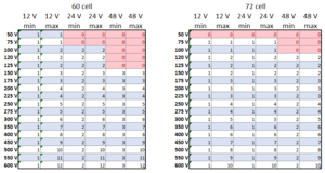
- Have PV source string voltage that does not exceed the maximum input voltage rating of the charge controller, even under extreme temperatures. This maximum input voltage rating limits the possible configurations of PV modules that can be used to reach the minimum number of PV modules calculated in Step 2. The chart below gives maximum and minimum numbers of PV modules in series per PV source circuit for 60 and 72 cell modules. All of the PV source circuits must have the same number of PV modules if there is a single charge controller or else it will not function properly (the number of modules in series therefore must divide evenly into the minimum number of PV modules required). If there are multiple charge controllers, then the number of modules connected in series per PV source circuit should be the same for each one. As long as the voltage doesn't exceed the rating of the charge controller(s), more PV modules per PV source circuit is generally preferrable as it permits smaller sized wires and minimizes voltage drop.
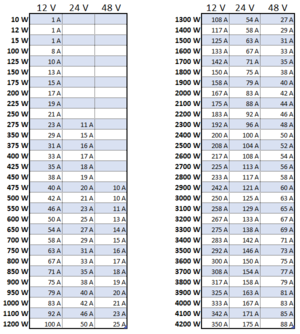
- Have a charge controller that can handle the total current supplied by the PV source. An MPPT charge controller is capable of of accepting varying voltages from the array and converting them into current at the proper charging voltage for the energy storage system. The maximum current of the PV source can be calculated by dividing the power rating of the PV source by the DC system voltage as in the chart below. Larger systems often require multiple charge controllers operating in parallel. The next largest charge controller size should be chosen unless the charge controller manufacturer permits oversizing the array. Common MPPT charge controller current ratings: 10 A, 15 A, 20 A, 25 A, 30 A, 35 A, 40 A, 45 A, 50 A, 55 A, 60 A, 65 A, 70 A, 75 A, 80 A, 85 A, 90 A, 95 A, 100 A.
- Can function at the DC system voltage. If a very high current rating is required for the charge controller, increasing the Special:MyLanguage/DC system voltage can yield a better system design.


Step 4: Final configuration
It is important to define a few important variables that will be necessary for future steps in the design process.
| Final number of PV modules in series | = |
|---|
| Final number of PV source circuits | = |
|---|
| Final PV source power rating | = PV module power rating (Step 1) × Final number of PV modules in series × Final number of PV source circuits |
|---|
| Final charge controller current rating | = |
|---|
Notes/references
- 60 cell Voc = 41 V
- 60 cell Vmp = 27 V
- 72 cell Voc = 50 V
- 72 cell Vmp = 34 V
- TkVoC = -0.36 %/C
- TkPmp = -0.48 %/C