Difference between revisions of "Simplified MPPT charge controller sizing and selection"
| Line 36: | Line 36: | ||
An MPPT charge controller will have a maximum input voltage rating that cannot be exceeded, even under extreme temperatures. This maximum input voltage rating limits the possible configurations of PV modules that can be used to achieve the desired [[Simplified minimum PV source size|minimum PV source size]]. A charge controller must be chosen that: | An MPPT charge controller will have a maximum input voltage rating that cannot be exceeded, even under extreme temperatures. This maximum input voltage rating limits the possible configurations of PV modules that can be used to achieve the desired [[Simplified minimum PV source size|minimum PV source size]]. A charge controller must be chosen that: | ||
#Can function at the [[DC system voltage]]. | #Can function at the [[DC system voltage]]. | ||
| − | #Can handle the | + | #Can handle the PV source circuit voltage. |
| + | #Can handle the total current supplied by the PV source. | ||
{| class="wikitable" border=1 style="width: 80%;" | {| class="wikitable" border=1 style="width: 80%;" | ||
Revision as of 11:58, 19 January 2021
A MPPT charge controller is rated to operate at a particular DC system voltage, maximum current and maximum voltage. MPPT charge controllers can charge the battery bank with any series and parallel configuration of modules that doesn't exceed the maximum voltage and maximum current or drop below the required charging voltage of the energy storage system. Exceeding the voltage rating of an MPPT due to cold temperatures can damage it. Many charge controllers allow the current rating to be exceeded to a certain point without damage, just lost energy - it depends on the charge controller. There are several important calculations that must be performed to properly size an MPPT charge controller:
- Should be sized to work with a series and parallel PV source circuit configuration of the PV source that will not damage the charge controller due to high voltages resulting from low temperatures at the project location.
- Should be sized to work with a series and parallel PV source circuit configuration of that will still be able to properly charge the energy storage system under high temperatures and as PV modules age at the project location.
Assumptions:
- Minimum ambient temperature: -15°C
- Maximum ambient temperature: 50°C
- Conservative estimates for PV module voltages are used that cover nearly all 60 and 72 cell solar modules.
Contents
Step 1: Determine PV module power rating
60-cell and 72-cell modules are the most common module size used with MPPT charge controllers. They range in size from 250W - 400W+.
Step 2: Determine minimum number of PV modules
This calculation will give a minimum number of modules. The final array size should always be larger than this value, thus if the result of the calculation is a decimal, it should be rounded up. Different modules sizes and configurations can be explored to find the optimal design.
| Minimum number of PV modules | = Minimum PV source size ÷ PV module power rating (Step 1) |
|---|
Step 3: PV source power rating
This calculation will give a power rating of the PV source based upon the chosen module size and the number of modules required.
| PV source power rating | = Minimum number of PV modules (Step 2) × PV module power rating (Step 1) |
|---|
Step 4: Determine minimum MPPT charge controller current rating
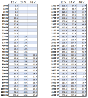
An MPPT charge controller is capable of of accepting varying voltages from the array and converting them into current at the proper charging voltage for the energy storage system. The maximum current of the PV source can be calculated by dividing the power rating of the PV source by the DC system voltage as in the chart below. Larger systems often require multiple charge controllers operating in parallel.
The next largest charge controller size should be chosen unless the charge controller manufacturer permits oversizing the array. Common MPPT charge controller current ratings: 10 A, 15 A, 20 A, 25 A, 30 A, 35 A, 40 A, 45 A, 50 A, 55 A, 60 A, 65 A, 70 A, 75 A, 80 A, 85 A, 90 A, 95 A, 100 A.
Step 5: Determine PV source series/parallel configuration
An MPPT charge controller will have a maximum input voltage rating that cannot be exceeded, even under extreme temperatures. This maximum input voltage rating limits the possible configurations of PV modules that can be used to achieve the desired minimum PV source size. A charge controller must be chosen that:
- Can function at the DC system voltage.
- Can handle the PV source circuit voltage.
- Can handle the total current supplied by the PV source.
| PV source power rating | = PV module power rating (Step 1) × Number of PV modules in series × Number of PV source circuits must be larger than minimum PV source size |
|---|
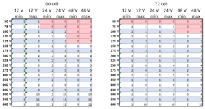
It is necessary to explore various module and charge controller configurations to find the optimal design. The chart below gives maximum and minimum numbers of PV modules in series for 60 and 72 cell modules.
Notes/references
- 60 cell Voc = 41 V
- 60 cell Vmp = 27 V
- 72 cell Voc = 50 V
- 72 cell Vmp = 34 V
TkVoC = -0.36 %/C TkPmp = -0.48 %/C

